Jtag pinouts for 7270v3?

zooster

Mitglied
Mitglied seit
4 Jan 2006
Beiträge
218
Punkte für Reaktionen
0
Punkte
0
Hi guys, my 7270v3 suddenly couldn't boot anymore. After a couple of seconds of power led blinking, instead proceeding with normal boot, 4 leds turn permanently on and dim (power, 2nd festnetz, wlan and info) and the box is unreachable and unusable. No ftpworking and no detection by the pc when connected via Lan for an usual recovery.
So now I can only try with Jtag. But unfortunately I couldn't find Jtag pinouts specific for 7270v3. I found pinouts for several models and versions, but not for v3.
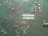
Can you please help me? I attached a picture of pads located under the board of my box.
Danke
 

Anhänge

  • uploadfromtaptalk1409602931969.jpg
    uploadfromtaptalk1409602931969.jpg
    129.2 KB · Aufrufe: 78
Zuletzt bearbeitet:
Ok, I attached the box to power supply and I used a multimeter to check shorts and voltages so here are my findings.
Would you help me to identify pins of jtag?


pinouts.jpg
 
Please have a look at the layout of a Speedport W503V.
It should be the same as used for the 7270V3.
The serial port is already connected by the coloured wires.
The complete port is described on this page.

Joe
 
Zuletzt bearbeitet:
Alternatively you could look here.
Regards,

JD.
 
Thank you guys for your reply. Unfortunately those links show only general information about jtag pinouts to connect to the board of the router, but they don't show which of those 2x14 pads on the board of my box is TDO, which is TDI, TMS, TCK, cTrst, Gnd and so on. And how many of them I should connect to jtag pinouts...
 
EJTAG-7270V3.jpg

Note: This is EJTAG, not JTAG. 'DINT' is not needed. Leave 'key' unconnected also.

G., -#####o:
 
Anhang anzeigen 77538

Note: This is EJTAG, not JTAG. 'DINT' is not needed. Leave 'key' unconnected also.

G., -#####o:

First of all thank you very much for your kind help.
This is my Jtag, although I bought v2 version. I thought to use it in buffered mode for wireless routers (config for tjtag software).
Following this scheme on my Jtag I've got: gnd, n_srst, tms, tck, tdi, n_trst, dint, tdo.

So I was wondering:
1) where should I connect n_srst of my Jtag? It's not present in your scheme.
2) this scheme for 7170 is very similar to yours, but it pictures a cTrst on pin 16 not present in your scheme... Is it present/important/to be used in my case? Because that link says that both the TRST and cTRST need to be connected to 3.3 volt via a 100 Ohm resistor... Is it still my case?
3) is 3v3 pin meant to be connect to my Jtag?
Thank you again.
 
Zuletzt bearbeitet:
zooster schrieb:
1) where should I connect n_srst of my Jtag? It's not present in your scheme.
This is 'RST'.

zooster schrieb:
2) ... Is it still my case?
Probably yes.

zooster schrieb:
3) is 3v3 pin meant to be connect to my Jtag?
You should setup your JTAG adapter in buffered mode. The buffer supply voltage is provided by your adapter itself (via the USB connector), so you don't need to connect the 3V3 pin.

G., -#####o:
 
This is 'RST'.

Probably yes.

You should setup your JTAG adapter in buffered mode. The buffer supply voltage is provided by your adapter itself (via the USB connector), so you don't need to connect the 3V3 pin.

G., -#####o:

So summarizing I have to connect: tdi, tms, tck, tdo, gnd, my n_srst to RST on the box, my n_trst to trst on the box + 100ohm to 3v3, and 100ohm from c_trst on the box (pin 16) to 3V3.
Is it right?
 
zooster schrieb:
So summarizing I have to connect: tdi, tms, tck, tdo, gnd, my n_srst to RST on the box ...
OK.

zooster schrieb:
... my n_trst to trst on the box + 100ohm to 3v3, and 100ohm from c_trst on the box (pin 16) to 3V3.
Should be wired this way (only one 100Ohm resistor):

EJTAG-7270V3-TRST.jpg

G., -#####o:
 
Thank you, I'll try and I'll let you know :)
 
Before beginning to use the jtag I decided to check again the pcb of box and since I've got another working v3 I compared them noticing two things:
1) the pcb of the "bricked" box is hot, almost untouchable. The working one is very warm but not untouchable.
2) on the working box, on all the jtag pads where I detected the voltage, I measured 3.20v, while on the "bricked" box the same measurement gives 2.99-3.00v.
So is this lower voltage normal, maybe because the box cannot boot, or is it rather due to an electric fault? Could it be a faulty voltage regulator?
Where can I check?
 
Zuletzt bearbeitet:
Hi! @ZOOSTER
I bought on EBAY 7270 V3 as defect about a year (maybe more) ago with same symptoms as yours.
After weeks of looking (& checking circuits) for damaged parts & not finding anything in particular damaged & decided to try power supply with more juice (amperage), hopping that if I missed any part it will pop. To my amazement, box booted successfully & working since then as a repeater.
I did check all the functions of the box & everything is working as it should.
Power supply has 12 Volts & 4 Amps of power & I always place my Fritzboxes on Notebook cooler.
I hope this helps.

I'll try, thanks.
 
Holen Sie sich 3CX - völlig kostenlos!
Verbinden Sie Ihr Team und Ihre Kunden Telefonie Livechat Videokonferenzen

Gehostet oder selbst-verwaltet. Für bis zu 10 Nutzer dauerhaft kostenlos. Keine Kreditkartendetails erforderlich. Ohne Risiko testen.

3CX
Für diese E-Mail-Adresse besteht bereits ein 3CX-Konto. Sie werden zum Kundenportal weitergeleitet, wo Sie sich anmelden oder Ihr Passwort zurücksetzen können, falls Sie dieses vergessen haben.